Belt transmission refers to gears
friction with a flexible connection and serves to
rotational motion transformations
with pulleys and drive belt
covering the pulleys.
Driving pulley by friction forces,
arising on the contact surface
pulley with a belt due to its tension,
drives the belt. Belt in
in turn makes it rotate
driven pulley. So the power
transmitted from the drive pulley to the driven pulley.
Types of belt drives
a - open transmission;b - cross
broadcast;
c - semi-cross
transmission (with
interbreeding
shafts);
g - angular gear (with
guiding
roller);
d - transmission from
pressure roller;
e - transmission from
stepped pulley
Classification of a belt drive according to the shape of the section
- flat belt(Fig. a);
- V-belt
(Fig. b);
- round-belt
(Fig. c);
- with gear
belts (fig. e);
- with polyclinic
belts (Fig. d).
Classification
In the direction of rotation of the pulley:with the same direction
(open and semi-open)
(Fig. 1a);
- with opposite
directions (cross)
(Fig. 1 b).
How to create tension
belt:
- simple (Fig. 1a);
- with a tension roller (Fig. 1 e);
- with a tensioner (see Fig. 2).
Fig.2. Belt tension adjustment
moving the engine: 1 - belt; 2
- pulley; 3 - tension device
Pulley design:
- with single-row pulleys (Fig. 1,
hell);
- with stepped pulleys (Fig. 1,
e).
Application area.
Belt drives are used to drive units fromelectric motors of small and medium power; for drive from low power
internal combustion engines. Most common in
mechanical engineering find V-belt drives (in machine tools,
motor vehicle engines, etc.). These transmissions are widely used in
small center distances and vertical axes of pulleys, as well as with
transmission of rotation by several pulleys.
If necessary, ensure a belt drive of a permanent
gear ratio and good traction ability is recommended
install toothed belts.
Flat belts have a rectangular section used in machines,
which must be resistant to vibrations (for example, high-precision
machines). Flat belt transmissions are currently used
relatively rare (they are replaced by V-belts). In theory
traction capacity of the V-belt at the same tension force by 3 times
more than flat.
Round-belt transmissions (as power ones) are not used in mechanical engineering.
They are mainly used for low-power devices in instrumentation and
household mechanisms (tape recorders, sewing machines, etc.).
Advantages:
- the possibility of location of the driving and driven pulleys onlong distances (more than 15 meters) (which is important, for example,
for agricultural engineering);
- smooth running, noiseless operation of the transmission,
due to the elasticity of the belt;
- low sensitivity to shocks and impacts, as well as to
overload, the ability to slip;
- the ability to work with high angular speeds;
- protection of mechanisms from sudden load fluctuations
due to the elasticity of the belt;
- the ability to work at high speeds;
- simple design and low cost.
Flaws:
- inconstancy of the gear ratio due tobelt slippage;
- gradual stretching of belts, their fragility;
- the need for constant care (installation and tension
belts, their alteration and replacement in case of a break, etc.);
- relatively large overall dimensions of the transmission;
- high loads on shafts and supports due to belt tension;
- danger of oil getting on the belt;
- low durability at high speeds (ranging from
1000 to 5000 hours);
- the need for a tensioner.
Flat transmission. Design and basic geometric relationships
Belt transmission with parallel,intersecting or crossing axes with
a flat drive belt is called
flat belt. On fig. 1 showing options
flat belt transmission. This transfer is simple
design, can operate at very high
speeds (up to 100 m/s) and large center
distances (up to 15 m). Due to the large
elasticity of the belt, it has a relatively
high durability. For flat belt drives
recommended to take and< 6 (с натяжным роликом
- to 10). Before the advent of V-belt transmission, flat belt transmission had a predominant
spreading.
Gear designs, flat belt
- open (see Fig. 1, a) - the simplest, most reliable andeasy-to-use transmission; it is applied when
parallel axes;
- cross (see Fig.1, 6) - used when
the need to rotate the pulleys in opposite
directions and parallel axes. Has an increased
belt edge wear. This transmission does not find
wide application;
- semi-cross (see Fig. 1, c) - transmission for
crossed axes;
- angular (Fig. 1, d) - recommended for
intersecting axes (mainly at an angle
90°).
Flat belt transmission materials.
General requirements for drive belt materials:wear resistance and strength under cyclic loads;
high coefficient of friction with pulleys; small module
elasticity and flexural rigidity.
These conditions are met by high-quality leather and
synthetic materials (rubber), reinforced
belting fabric (GOST 6982-54), polymer (nylon,
polyamide C-6, rubber SKN-40, latex) or metal
cord. Rubberized fabric belts are used (GOST
101-54), layered cutting belts with rubber layers,
layered and spirally wrapped belts. In damp areas
and aggressive environments use belts with rubber
gaskets.
Pulleys are made of cast iron grade SCH10, SCH15, SCH25, etc.
The pulley of welded structures is made of steel grades St1, St2
etc. For lightweight pulleys, use
aluminum alloys, textolites. Leather belts are made from animal skin (the skin is subjected to special tanning). These belts have high traction power,
elasticity and wear resistance, allow smaller pulley diameters.
However, due to scarcity and high cost, they are currently
rarely used, only for especially critical structures. The basis
rubberized belt - durable cord provulcanized
technical cotton fabric in 2-9 layers linked together
vulcanized rubber. fabric with a higher modulus of elasticity
than rubber, transfers the bulk of the load. Rubber Boost
coefficient of friction, ensures the operation of the belt as a whole and
protects the fabric from damage and abrasion during transmission operation.
Due to strength, elasticity, low sensitivity to moisture and
temperature fluctuations rubberized belts are widespread.
Depending on the option of laying the fabric base before vulcanization
belts are divided into three types (Fig. 4): A - threaded (the fabric is cut in width
belt), are used most often, belt speed up to 30 m/s; B -
layer-wrapped, used for heavy duty applications
speeds up to 20 m/s; B - spirally wrapped, used for small
loads and speeds up to 15 m/s, provides increased
edge wear resistance. The most flexible Type A belts, they got
predominant distribution. .
Textile belts (cotton and
woolen) are suitable for work in the atmosphere
dusty, saturated with alkali vapors, gasoline,
with sharp fluctuations in load, but traction
their ability is relatively low.
Films are widely used
nylon or twill belts with friction
coated (film). High static and
fatigue strength of synthetic materials gave
the possibility of reducing the thickness of the belt.
Synthetic fabric belts are made from
kapron or nylon fabric. These belts have
low weight and high coefficient of friction.
They are used in high-speed drives and
ultra-fast gears (< 100 м/с).Rubberized
belts of all types
are made without
rubber linings
(for normal
working conditions), so
and with covers (for
work in damp
premises, as well as
in an environment saturated
pairs of acids and
alkalis). Cotton belts are made
weaving looms from cotton yarn in
several interlacing layers (four-eight) followed by impregnation
azokerite and bitumen. Cotton
belts are less expensive than
rubberized.
Woolen belts are made from wool
yarn woven and stitched
cotton yarn impregnated
composition of drying oil, chalk and iron minium.
The load capacity of these belts is higher,
than cotton ones. Find application
in the chemical industry.
Pulley structures.
Pulleys are made of cast iron,steel, welded or prefabricated, cast from
light alloys and plastics. Pulley diameters
determined from the calculation of the belt drive, and
then rounded up to the nearest value from the series
R40 (GOST 17383-73*). Cast iron pulleys are used
at speeds up to 30÷45 m/s. Small pulleys
diameters up to 350 mm have solid discs,
large diameter pulleys - hubs
elliptical variable section. Steel
welded pulleys are used at speeds of 60÷80
m/s. Light alloy pulleys are promising for
high-speed gears up to 100 m/s.
The main geometric parameters of belt drives
Angles α1 and α2 ,relevant
the arcs along which
there is a touch
belt and rim
pulley, called
grip angles.
Calculation of geometric parameters.
. center distancewhere L is the estimated length of the belt; D1 and D2 - diameters
driving and driven pulleys.
For the normal operation of the flat belt drive
condition must be met:
while a should be no more than 15 m. 2. Estimated belt length
another 100-300 mm is added to the stitching.
3. Diameter of the driving pulley (small), mm
(Where
P1 - power) 4. Driven pulley diameter
where and - gear ratio;
- slip coefficient.
With a diameter D > 300 mm, pulleys are made with
four to six needles. For pulleys with
deviations from standard sizes, produce
strength calculation. Rim count on
strength as a freely rotating ring under
the action of inertial forces; spokes count on
bend. Permissible wrap angles for belt drives. Due to stretching and
belt slack during operation, wrap angles are measured
approximately:
(6)
In formula (6), the expression
(7)
where β is the angle between the branches of the belt (for
flat belt transmission (β< 30°)). Угол β между
belt branches affects the value of the wrap angles (α1 and
α2). It is also recommended to accept the value
pulley diameters (D1 and D2) to comply with
condition
(8)
where for flat belt transmission [α ]= 150°, for
V-belt [α] - = 120°. Gear ratio.
In a belt drive, as in a friction drive, as a result
elastic sliding belt circumferential speeds are not the same.
Hence the gear ratio
where, ω1 and n1 are the angular velocity and rotation frequency of the master
pulley; , ω2 and n2 - the same, driven pulley; , D1,D2 - diameters
driving and driven pulleys; ε- slip coefficient.
The relative loss of speed on the pulleys is characterized by
slip coefficient; with a small value
this coefficient (ε< 0,02) приближенно имеем (10)
belt drive efficiency. Taking into account losses during operation, efficiency
transfers are determined from the expression
where Ψу - relative losses associated with slip on
pulleys and due to the elasticity of the belt; Ψnn- relative
bearing losses; Ψsv - relative losses from resistance
air (taken into account only with large pulleys with spokes).
If the known power on the driving pulley and the power on
slave (reduced due to losses), then the transmission efficiency
for flat belt open gear average value
efficiency 0.96-0.98; for V-belt transmission 0.95-0.96; For
gears with a tension roller 0.95.
belt drive is called a kinematic mechanism that transmits energy using a flexible connection using friction between the belt and the pulley.
Components belt drive are the driving and driven pulleys located at some distance from each other, which are wrapped around by a special drive belt.
The level of the transmitted load at belt drive depends on factors such as belt tension, coefficient of friction and sheave angle.
Belt drives
Belt drives There are various types and are classified depending on the shape of the cross section of the belt. According to this criterion, experts distinguish between round-belt, V-belt and flat-belt transmissions. At the same time, wedge-shaped and flat belts are the most common in technology.
The main advantage of flat belts is that their tension at the points of contact with the pulleys is minimal, and wedge-shaped belts are that, due to their profile, they are characterized by increased traction. As for round belts, they can most often be found in machines and mechanisms that have relatively little big sizes, for example, devices, desktop machines, equipment for the food and clothing industry.
Advantages and disadvantages of belt drivesThe main advantages that have belt drives, are the following: simple design and low cost; the possibility of ensuring the transmission of torque over long distances; ease of operation and maintenance; smooth operation and smooth running.
At the same time, belt drives have a number of disadvantages, which include: relatively large dimensions that do not allow their use in a number of cases; fragility when used on high-speed mechanisms; the impossibility of ensuring a constant gear ratio due to belt slippage; heavy loads on supports and shafts.
It should also be emphasized that the reliability belt drives significantly lower than other types of transmissions, since belt breaks and their jumping off the pulleys are not excluded and quite often occur. That is why belt drives require more attention in terms of maintenance, and they need to be constantly monitored.
Types of flat belt drivesDepending on how the axes of the pulleys are located, as well as on their purpose, flat belt drives are divided into the following types: open gears, gears with stepped pulleys, cross gears and gears with a tension roller.
Open gears are characterized by parallel axes and the fact that the pulleys rotate in the same direction.
Gears with stepped pulleys provide the ability to change the angular speed of rotation of the driven shaft at a constant speed of the drive shaft.
In cross gears, the pulleys rotate in opposite directions, and their axes are parallel.
Gears with a tension roller provide automatic belt tension and an increase in the angle of wrapping of a pulley with a small diameter.
The main materials for the manufacture of flat belts are leather, woolen, rubberized and cotton fabrics, and they can have different widths. Which of them are used in each case depends on the purpose of the belt and the conditions of its operation. In addition, the load that the belt will experience during the operation of the transmission is also of no small importance.
The design of a flat belt transmission is relatively simple, it can be successfully used when high speed characteristics of kinematic mechanisms and large distances between the axes of the pulleys are required.
V-belt transmissionThe main feature of a V-belt transmission is that its drive belt has a trapezoidal section with a profile angle equal to 40°. Compared to a flat type belt, it is capable of transmitting sufficiently large traction forces, however efficiency it is significantly lower.
The main function of any drive belt is to transmit traction, and therefore it needs to be strong, wear-resistant, durable, provide good grip on the pulleys, and at the same time be relatively inexpensive.
The main area of use of V-belt transmissions is machines and mechanisms with small center distances and large gear ratios. In this case, the shaft axes are most often located in a vertical plane.
timing beltsTiming belts are most often made of such a durable and modern synthetic material as polyamide. They quite successfully combine the advantages that gearing and flat belts have.
These belts have small protrusions on their working surfaces, which, during operation, enter into small recesses located on the pulleys. They are well suited for those gears that transmit rotation at high speeds, and the center distance is small.
Belt pulleysFor flat belt drives, the most preferred shape of the working surface that the pulley has is smooth surface, which has some convexity. As for V-belts, their working surfaces are the side surfaces of the pulleys. Pulleys are made from materials such as steel, plastics, aluminum alloys and cast iron.
Belt transmissions are friction (friction) transmissions, in which power is transferred due to friction forces that arise between the driving, driven and intermediate link - an elastic belt (flexible connection).
The driving and driven links are commonly referred to as pulleys. This type of gear is usually used to connect shafts located at a considerable distance from each other.
For normal operation of the belt drive, it is necessary to pre-tension the belt, which can be carried out by moving one of the pulleys, by means of tension rollers or by installing the engine (mechanism) on a rocking plate.
Belt drive classification
Belt drives are classified according to various criteria - according to the shape of the cross section of the belt, according to the relative position of the shafts and the belt, according to the number and type of pulleys, according to the number of pulleys covered by the belt, according to the method of adjusting the belt tension (with an auxiliary roller or with movable pulleys).
1. According to the shape of the cross section of the belt There are the following types of belt drives:
- flat-belt (the cross section of the belt has the shape of a flat elongated rectangle, Fig. 1a);
- V-belt (cross section of a belt in the form of a trapezoid, Fig. 1b);
- poly-V-belt (the belt outside has a flat surface, and the inner, interacting with the pulleys, the surface of the belt is equipped with longitudinal ridges, made in cross section in the form of a trapezoid, Fig. 1d);
- round-belt (the cross section of the belt has a round or oval shape, Fig. 1c);
- toothed belt (the inner surface of the flat belt in contact with the pulleys is provided with transverse protrusions that enter the corresponding pulley cavities during the operation of the transmission, photo below).
V-belts and V-ribbed belts are most widely used in mechanical engineering. Transmission round rubber belt (diameter 3…12 mm) used in low power drives (desktop machines, appliances, household machines, etc.).
A variation of the belt drive is a toothed belt drive, in which power is transmitted by a toothed belt by meshing the teeth of the belt with the protrusions on the pulleys. This type of gear is intermediate between gear and friction gears. The toothed belt drive does not require significant belt pretensioning and does not have the disadvantage of belt slip that is inherent in all other belt drives.
V-belt transmission is mainly used as an open one. V-belt drives have a greater traction capacity, require less tension, due to which they load the shaft supports less, allow smaller wrap angles, which allows them to be used with large gear ratios and a small distance between the pulleys.
V-belts and V-ribbed belts are endless and rubberized. The load is carried by a cord or fabric folded in several layers.
V-belts are produced in three types: normal section, narrow and wide. Wide belts are used in variators.
V-ribbed belts are flat belts with a high-strength cord and internal longitudinal wedges included in the grooves on the pulleys. They are more flexible than wedges, better ensure the constancy of the gear ratio.
Flat belts have great flexibility but require significant belt pretensioning. In addition, a flat belt is not as stable on a pulley as a V-belt or poly V-belt.
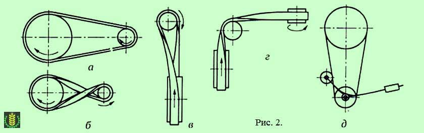
2. According to the mutual arrangement of the shafts and the belt :
- with parallel geometric axes of the shafts and a belt covering the pulleys in one direction - open transmission (pulleys rotate in the same direction, fig. 2a);
- with parallel shafts and a belt covering the pulleys in opposite directions - cross transmission (pulleys rotate in opposite directions, Fig. 2b);
- shaft axes intersect at some angle (most often 90°, Fig. 2c) – semi-cross transmission;
- the transmission shafts intersect, while changing the direction of the transmitted power flow is carried out by means of an intermediate pulley or roller - corner gear(Fig. 2d).
3. By the number and type of pulleys used in transmission: with single-pulley shafts; with a two-pulley shaft, one of the pulleys of which is idle; with shafts carrying stepped pulleys for changing the gear ratio (for stepping the speed of the driven shaft).
4. By the number of shafts covered by one belt : two-shaft, three-, four- and multi-shaft transmission.
5. By the presence of auxiliary rollers : without auxiliary rollers, with tension rollers (Fig. 2e); with guide rollers (Fig. 2d).
Advantages of belt drives
The advantages of belt drives include the following properties:
- Simplicity of design, low cost of manufacture and operation.
- The ability to transmit power over a considerable distance.
- Ability to work with high speeds.
- Smoothness and small noise in work owing to elasticity of a belt.
- Mitigation of vibration and shocks due to the elasticity of the belt.
- Protection of mechanisms from overloads and shocks due to the ability of the belt to slip (this property does not apply to gears with a toothed belt).
- The electrical insulating capacity of the belt is used to protect the driven part of electrically driven machines from the occurrence of dangerous voltages and currents.
Disadvantages of belt drives
The main disadvantages of belt drives:
- Large overall dimensions (especially when transferring significant capacities).
- Low belt durability, especially in high-speed gears.
- High load on the shafts and bearings of the supports due to belt tension (this disadvantage is less pronounced in toothed belt drives).
- The need to use belt tensioning devices that complicate the design of the transmission.
- Sensitivity of the load capacity to contamination of links and air humidity.
- Non-constant gear ratio due to the inevitable elastic sliding of the belt.
Scope of belt drives
Belt drives are used in most cases to transmit movement from an electric motor or an internal combustion engine,  when, for design reasons, the center distance should be large enough, and the gear ratio may not be strictly constant (conveyors, drives of machine tools, road and agricultural machines, etc.). Gears with a toothed belt can also be used in drives that require a constant gear ratio.
Power transmitted by belt drive, typically up to 50 kW, but can reach 2000 kW and even more. Belt speed v = 5…50 m/s, and in high-speed transmissions - up to 100 m/s and higher.
After gear transmission, belt transmission is the most common of all mechanical transmissions. It is often used in combination with other types of transmissions.
Geometric and kinematic ratios of belt drives
Center distance a of the belt drive determines mainly the design of the drive of the machine. Recommended center distance (see Fig. 3) :
For flat belt drives:
a ≥ 1,5 (d 1 + d 2) ;
For V-belt and poly V-belt drives:
a ≥ 0,55 (d 1 + d 2) + h;
Where:
d 1, d 2 are the diameters of the driving and driven transmission pulleys;
h is the height of the belt section.
Estimated belt length L p equal to the sum of the lengths of the straight sections and the arcs of the circumference of the pulleys:
L p = 2 a + 0,5 π(d 2 + d 1) + 0,25 (d 2 - d 1) 2 / a.
According to the found value from the standard series, the nearest greater estimated belt length L p is taken. When connecting the ends, the length of the belt is increased by 30…200 mm.

Center distance in belt drive for the finally installed belt length is determined by the formula:
a = [ 2 L p - π(d 2 + d 1)] / 8 + √{[ 2 L p - π(d 2 + d 1)] 2 - 8 π(d 2 - d 1) 2 )/ 8 .
Small pulley belt wrap angle
α 1 = 180 ° - 2 γ .
From a triangle O 1 IN 2(Fig. 3)
sin γ \u003d IN 2 / O 1 O 2 \u003d (d 2 - d 1) /2 a.
In practice, γ does not exceed π/ 6 , therefore, approximately take sin γ = γ (rad), then:
γ \u003d (d 2 - d 1) / 2 a (rad) or γ ° = 180 °(d2 –d1)/ 2 pa.
Hence,
α 1 = 180 ° - 57 ° (d 2 - d 1) / a.
Belt drive ratio:
u \u003d i \u003d d 2 / d 1 ( 1 – ξ) ,
where: ξ is the gear slip coefficient, which during normal operation is equal to ξ = 0.01…0.02.
Approximately, you can take u = d 2 /d 1; ξ \u003d (v 1 -v 2) / v 1.
On fig. 1 shows the kinematic diagram of the V-belt transmission. To calculate the transmission, the initial data are required, which are given below.
Initial data: power and torque on the transmission drive shaft R 1 And T 1, frequency of rotation of the driving pulley n 1, gear ratio u, the nature of the load, the location of the transmission in space (horizontal, inclined or vertical), design requirements.
1. The type of belt section is selected. By size R 1 And n 1 using the diagram, fig. 2. Belts with a larger cross-sectional area have more load capacity but are less flexible, resulting in a larger diameter pulley. Selecting a belt with a smaller cross-sectional area will result in smaller transmission dimensions, but with a larger number of belts.
 Rice. 2
2. The diameter of the drive pulley is selected, d1 according to table 1. For each section of the belt, the recommended range of values is given d1. Smaller values should be taken in the case when it is necessary to obtain small transmission dimensions, but in this case the bending stresses in the belt will be the largest, which will lead to an increase in the number of belts.
Meaning d1 should be taken according to GOST, table 2, or from a number of numbers recommended for sizes, table 3.
Table 1
| Section designation | Section dimensions, mm | Sectional area, A, mm 2 | Belt length, mm | Base length, mm | Pulley diameter, d 1, mm | ||||
| b | bp | h | y 0 | dmin | Recommended, d 1 | ||||
| 0 (Z) | 8,5 | 2,1 | 400 - 2500 | 71, 80, 90, 100 | |||||
| A (A) | 2,8 | 560 - 4000 | 100, 112, 125, 140, 160 | ||||||
| B (B) | 10,5 | 800 - 6300 | 140, 160, 180, 200, 224 | ||||||
| B (C) | 13,5 | 4,8 | 1800 - 10000 | 224, 250, 280, 315, 355 | |||||
| G (D) | 6,9 | 3150 - 15000 | 355, 400, 450, 500, 560 | ||||||
| D (E) | 23,5 | 8,3 | 4500 - 18000 | 560, 630, 710, 800, 900 |
Note: in parentheses are the designations of belts in the international ISO system.
The dimensions of the belt section are shown in fig. 3.
table 2
3. The diameter of the driven pulley is determined, approximately
The resulting value is rounded up to the nearest GOST, table 2, if the drive is designed for mass production. In other cases, including in educational design, the values of diameters can be taken from a series of numbers, table 3.
4. The gear ratio is specified taking into account the slip coefficient e
can be accepted ε =0.01…0.02. Value Deviation u up to 4% of the specified value is allowed.
5. Pre-determined center distance, mm.
The center distance of belt drives can be set within a wide range. From the value A belt length depends. It can be preliminarily determined depending on the gear ratio u and diameter d2 according to table 4, .
Table 4
| Center distance values, a, mm | ||||||
| u | ||||||
| a | 1.5d2 | 1.2d2 | d2 | 0.95d2 | 0.9d2 | 0.85d2 |
If necessary, the smallest or greatest value center distance can be determined by the formulas:
Where h– belt height, mm, table 1.
![]()
However, the center distance should be taken under certain requirements for the dimensions of the transmission. In practical calculations, if there are no special requirements for the dimensions of the transmission, it is recommended to take a value not less than that obtained from Table 4. The value of the center distance, chosen close to, can create difficulties in the layout of the drive, as well as in the design of the tension mechanism.
6. Estimated belt length
![]() , mm
, mm
the value of the belt length is selected according to GOST, table 5. If there are no special requirements for the dimensions of the transmission, then it is recommended to choose l close to the calculated value, preferably a larger value. Increasing the length of the belt helps to reduce the number of loading cycles and increase the service life of the belt, but at the same time the dimensions of the transmission increase.
Table 5
7. The center distance is specified,
8. Wrap angle of the smaller pulley, a, deg.,
![]() .
.
Angle a for V-belt transmissions must be at least 120 °, with smaller values, the traction ability of the transmission is reduced.
9. The circumferential speed is determined, V
10. Rated power R o transmitted by one belt, provided: a\u003d 180 about, u=1, load without fluctuations, for the basic length of the belt, is selected according to table 6.
Table 6
Power P 0 , kW, transmitted by one belt.
| Belt section | Estimated diameter of a small pulley, mm | Belt speed, m/s | |||||||||
| 0 (Z) | 0,23 | 0,29 | 0,36 | 0,42 | 0,49 | 0,56 | 0,62 | 0,69 | 0,75 | 0,82 | |
| 0,24 | 0,32 | 0,39 | 0,47 | 0,55 | 0,63 | 0,71 | 0,78 | 0,85 | 0,93 | ||
| 0,29 | 0,37 | 0,45 | 0,53 | 0,61 | 0,69 | 0,77 | 0,85 | 0,92 | 1,00 | ||
| 0,31 | 0,41 | 0,49 | 0,58 | 0,67 | 0,76 | 0,85 | 0,93 | 1,03 | 1,11 | ||
| A (A) | 0,52 | 0,66 | 0,74 | 0,88 | 1,03 | 1,10 | 1,25 | 1,33 | 1,40 | 1,47 | |
| 0,52 | 0,66 | 0,81 | 0,96 | 1,10 | 1,18 | 1,33 | 1,40 | 1,47 | 1,62 | ||
| 0,52 | 0,66 | 0,81 | 0,96 | 1,10 | 1,25 | 1,40 | 1,47 | 1,54 | 1,69 | ||
| 0,59 | 0,74 | 0,96 | 1,10 | 1,25 | 1,40 | 1,54 | 1,69 | 1,84 | 1,99 | ||
| B (B) | 0,74 | 0,96 | 1,10 | 1,33 | 1,47 | 1,69 | 1,92 | 2,06 | 2,28 | 2,42 | |
| 0,81 | 1,08 | 1,25 | 1,40 | 1,62 | 1,84 | 2,06 | 2,23 | 2,42 | 2,65 | ||
| 0,96 | 1,18 | 1,40 | 1,62 | 1,84 | 1,99 | 2,20 | 2,50 | 2,72 | 2,94 | ||
| 1,10 | 1,33 | 1,55 | 1,77 | 1,99 | 2,20 | 2,50 | 2,72 | 2,92 | 3,16 | ||
| B (C) | 1,40 | 1,77 | 2,14 | 2,50 | 2,80 | 3,10 | 3,40 | 3,68 | 3,98 | 4,35 | |
| 1,62 | 2,06 | 2,42 | 2,88 | 3,16 | 3,54 | 3,90 | 4,24 | 4,64 | 5,00 | ||
| 1,77 | 2,20 | 2,65 | 3,10 | 3,54 | 3,90 | 4,27 | 4,64 | 5,10 | 5,45 | ||
| 1,84 | 2,36 | 2,88 | 3,32 | 3,76 | 4,20 | 4,57 | 5,00 | 5,45 | 5,90 | ||
| G (D) | - | - | 4,71 | 5,45 | 6,25 | 7,00 | 7,65 | 8,45 | 9,19 | 9,70 | |
| - | - | 5,15 | 5,96 | 6,85 | 7,65 | 8,39 | 9,20 | 9,87 | 10,44 | ||
| - | - | 5,59 | 6,48 | 7,38 | 8,24 | 9,19 | 10,08 | 10,90 | 11,54 | ||
| - | - | 6,10 | 6,94 | 7,93 | 8,90 | 9,92 | 10,98 | 11,78 | 12,50 |
Note: belt designations in the international ISO system are given in brackets.
V-belts are made in the form of a closed endless belt. For general purpose gears according to GOST 1284.1-89, seven types of V-belts 0, A, B, C, D, D, E are produced, differing in cross-sectional dimensions. The section dimensions increase accordingly from type 0 to E.
11. Power transmitted by one belt R p in the operating conditions of the calculated transmission
![]() , kW,
, kW,
Where: With a wrap angle factor, table 7, C l belt length factor, table 8, C u gear ratio, table 9, C p load mode factor, table 10.
Table 7
Table 8
Table 9
Table 10
12. The number of belts is determined, z
Where: C z belt number coefficient, table 11.
First determine z excluding coefficient Cz, and then specify the number of belts z.
Table 11
An integer number of belts is accepted. Recommended z£6, because belts and grooves are subject to inevitable deviations. The more belts, the greater the uneven tension and loading them. Additional slips, wear and loss of power appear in the transmission.
If the number of belts is fractional, then the choice z recommended under the following conditions:
If the fractional part is less than 0.2, then z can be rounded down, which will lead to a slight decrease in the term belt service,
If the fractional part is greater than 0.8, then z should be rounded up, which will lead to some increase in the durability of the belts,
If the fractional part is from 0.2 to 0.8, then the calculation should be repeated by changing the diameters of the pulleys and the length of the belt, according to the recommendations given above. So you can get the value z close to an integer.
13. Pre-tensioning each strand of the belt, F o
The installation of the belt tension and its control during the operation of the transmission is most simply carried out according to the deflection of the belt branch under the action of a certain load. The definition of the deflection and the measurement scheme is given in Appendix 3.
14. District power
15. The forces acting in the branches of the belt are determined (per one belt)
![]() , H,
, H,
![]() , N.
, N.
16. The force acting on the shafts and bearings from the preload is determined, F in
![]() , H.
, H.
The magnitude of this force can later be used in determining the support reactions, calculating the shafts, and determining the durability of the bearings.
17. Frequency of belt runs
permissible number of runs for V-belts recommended =10 s -1 . If condition n p £ is not satisfied, the length of the belt should be increased.
18. The main dimensions of the pulleys are determined, table 12, their design is developed, the method of mounting on the shafts is selected.
Table 12
V-belt pulleys
Groove profiles for normal section belts and their dimensions
| Belt section | c | e | t | b | Estimated diameters at an angle φ o | |||
| 2,5 | 7,5 | 63-71 | 80-100 | 112-160 | ||||
| A | 3,3 | 90-112 | 125-160 | 180-400 | ||||
| B | 4,2 | 12,5 | 125-160 | 180-224 | 250-500 | |||
| IN | 5,7 | 14,5 | 22,5 | - | 200-315 | 355-630 | ||
| G | 8,1 | - | 315-450 | 500-900 | ||||
| D | 6,9 | 23,5 | 44,5 | - | 500-560 | 630-1120 | ||
| E | 12,5 | - | - | 800-1400 |
Note: Material of pulleys - cast iron SCH 15, steel 25 L.
Roughness of working surfaces Ra< 2,5 мкм.

19. The method of belt tension is selected.
Belt tensioning methods.
The transmission of torque from the drive pulley to the belt and from the belt to the driven pulley occurs due to the friction force between the belt and the pulley. The friction force depends on the pre-tensioning of the belt, which is carried out in the following ways:
1. Periodically tightening the belt (as it is pulled out) with a screw, by moving the electric motor along the slide (Appendix 1, Fig. 1). Periodic tension adjustment requires systematic monitoring of the transmission, and if the tension decreases, slipping may occur, which will lead to rapid belt wear. However, this method is most often used in practice. Slider parameters are given in the table (Appendix 2).
2. A tension roller installed on the outside of the driven branch of the belt closer to the small diameter pulley (Appendix 1, Fig. 2). This helps to increase the wrap angle of the small pulley. The tension roller can be pressed periodically or with the help of a spring. The disadvantage of this method is the bending of the belt in reverse side, which accelerates the process of fatigue failure of the belt. For V-belt drives, this method is practically not used.
3. Under the action of gravity of an electric motor mounted on a swinging plate and a screw device, (Appendix 1, Fig. 3).
4. Automatically through the use of a gear pair in combination with a belt drive. The method is rarely used due to the complexity of the design.
The belt tension value has a significant impact on durability, traction and transmission efficiency.
When designing a tensioner, it is necessary to determine the course of the pulley, which ensures that the belt is put on and tensioned.
Reducing the center distance for putting on the belt is recommended to take depending on the length of the belt, and increase when the belt is tensioned. The design of the skid should provide sufficient pulley travel with a margin.
Calculation results should be presented in the form of a table containing the main transmission parameters, as well as pulley sketches.
3. An example of the calculation of V-belt transmission
Initial data: drive pulley power R 1= 7 kW, torque on the driving pulley T 1= 45.5 Nm, drive pulley speed n 1\u003d 1470 min -1, gear ratio u= 3, load nature: moderate fluctuations occur (e.g. belt conveyor drive).
16. Force acting on the shaft and bearings F in
15. Frequency of belt runs
![]() from -1<
,
=10 s -1 .
from -1<
,
=10 s -1 .
15. The main dimensions of the pulleys are determined, their design is being developed

Pulley width IN=63 mm, outer diameters of pulleys D1=148.5 mm, D2=428.5 mm.
Calculation results
Belt section type B
Estimated pulley diameters, mm d1=140, d2=420
gear ratio u=3,03
Belt length, mm l=2000
Center distance, mm A=542
Number of belts z=3
Peripheral speed, m/s V=10,8
Circumferential force, N F t=648,15
Pretension force, N F0=221
Force acting on shafts and bearings, N F in=1282,3
The number of runs of the belt in 1 second. n p=5,4
The theoretical foundations of the calculation are common to all types of belts.
Performance criteria and calculation. The main criteria for the performance of belt drives are: pulling ability, determined by the friction force between the belt and the pulley, belt durability, which in normal use is limited to belt failure due to fatigue.
Currently the main calculation of belt drives is the calculation of traction. The durability of the belt is taken into account in the calculation by choosing the main transmission parameters in accordance with the recommendations developed by practice.
Kinematic parameters. Peripheral speeds on pulleys
; ![]() .
.
Taking into account the elastic sliding of the belt, one can write either
![]() ,
,
where is the slip coefficient. At the same time, the gear ratio
In the following, it is shown that the value depends on the load, therefore, in a belt drive, the gear ratio is not strictly constant. Under normal operating loads 0.01. ..0.02. A small value allows one to take approximately