Belt drives
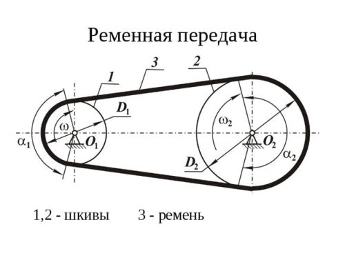
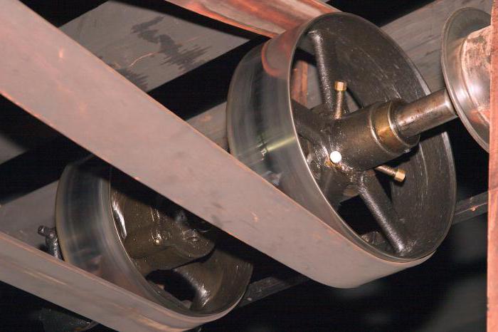
Belt drive (Fig. 4.58, a) consists of driving and driven pulleys connected by a belt (belts) put on tensioned pulleys. The rotation of the drive pulley will be transferred to the driven one due to the friction developed between the drive
Rice. 458
belt and pulleys or meshing (toothed belt drive).
Advantages: the possibility of transferring between shafts located at a considerable distance; smooth and quiet operation; overload protection is related to the ability of the belt to transmit only a certain load, above which slipping (sliding) of the belt against the pulley occurs; low cost and ease of maintenance of the transmission.
Disadvantages: large overall dimensions; inconstancy of the gear ratio due to belt slippage; increased pressure forces on shafts and bearings, since the total tension of the belt branches is much greater than the circumferential transmission force; low durability of belts and the need to protect them from oil; the need for belt tensioners.
In most cases, belt drives are used to transmit powers of 0.3–50 kW: the efficiency for a flat belt transmission is β = 0.96, and for a V-belt transmission β = 0.95.
According to the cross-sectional shape, friction drive belts are divided into flat (Fig. 4.586), wedge (Fig. 4.58, c), poly-V-ribbed (Fig. 4.58, G), round (Fig. 4.58, e) and etc.
Accordingly, according to the shape of the cross-section of the belt, flat-belt, V-belt, poly-V-belt and round-belt transmissions are distinguished.
Materials and designs of belts. The drive belt must have a certain traction capacity (the ability to transmit a given load without slipping) and the required durability. The traction capacity of the belt is ensured by its reliable adhesion to the pulleys, which is determined by the high coefficient of friction between them. The durability of a belt depends on the bending stresses that occur in it and the frequency of loading cycles. But the material and design distinguish several types of belts.
Flat straps. Standard flat belts include rubberized fabric, leather, cotton woven and wool. The ends of flat belts can be connected (by stitching, gluing, metal clips), and seamless (endless) are used in high-speed transmissions.
V-belts. They are made of three types: normal section, narrow and wide for variators. Normal section belts are the main ones in general engineering. In accordance with GOST, these belts are manufactured in seven sections of different sizes: O, A, B, C, D, D and E. The maximum speed allowed for profiles O, A, B, C is up to 25 m / s, for G, D and E - up to 30 m/s. Sections of belts increase from O to E. V-belts are widely used in industry.
V-ribbed belts. By design, they are similar to wedges. In their thin flat part (see Fig. 4.58 and 4.59, a) a high-strength cord cord made of viscose, fiberglass or lavsan and several layers of diagonally located fabric are placed, giving the belt a greater transverse rigidity. V-ribbed drives are the most compact of all belt drives and can run at speeds v≤ 40 m/s.
timing belts (Fig. 4.59, b). They combine the advantages of flat belts and gears. On the working surface of the belts, protrusions (teeth) are made that engage with the protrusions (teeth) on the pulleys. Toothed belts are installed without pretensioning. They operate silently with no slippage and have a constant gear ratio. Compared to the usual

Rice. 4.59
belt drive by friction, toothed belts are much more compact and have a higher efficiency.
Materials and designs of pulleys. Belt pulleys are made from cast iron, steel, light alloys, plastics and wood. The outer part of the pulley, on which the belt (belts) are installed, is called the rim, and the central part, mounted on the shaft, is called the hub. The rim with the hub is connected by a disk or spokes.
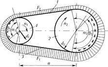
Kinematics, geometry and forces in belt drives. The belt loading diagram is shown in fig. 4.60, where is the angle of the belt around the pulley; a– center distance; – sliding arc, on which elastic sliding is observed.
Tension force of the leading branch 3 belt running off the driven pulley 2 during the operation of the transmission, more tension force one hundred driven branch 1, running on the driven pulley 2. From the distribution of forces in the cross sections of the belt it follows that on the drive pulley 1 the tension force gradually decreases, and on the driven 2 - increases. Different tensions of the driving and driven branches of the belt causes elastic sliding of the belt on the pulleys.
Peripheral speeds (m / s) of the leading g;) and the slave v 2 pulleys are determined by the formulas
![]()
where is the rotational speed, rpm; is the diameter of the ιth pulley, mm.
Due to the elastic sliding of the belt on the pulleys on the driving pulley, the peripheral speed is greater than the peripheral speed on the driven:
Rice. 4.60
where is the coefficient of elastic slip. Elastic slip lies within and increases with increasing load.
The gear ratio of the belt drive, taking into account slippage, is determined as follows.
The procedure for calculating belt drives
Initial data (obtained from the kinematic calculation of the drive):
N 1 - power on the drive shaft;
n 1 - frequency of rotation of the drive shaft, rpm;
and- gear ratio of the belt drive.
1. According to table 4.3.1, select the belt section depending on the torque on the drive shaft:
T 1 = 9555∙10 3 ∙ , H∙mm. (4.3.1)
pulley diameters when choosing belts
| Belt section | T 1 , N∙mm | d min , mm | Belt section | T 1 , N∙mm | d min , mm |
| Wedge normal section | Wedge narrow | ||||
| O | Up to 30∙10 3 | UO | Up to 150∙10 3 | ||
| BUT | 15∙10 3 …60∙10 3 | UA | 90∙10 3 …400∙10 3 | ||
| B | 50∙10 3 …150∙10 3 | UB | 300∙10 3 …2∙10 6 | ||
| AT | 120∙10 3 …600∙10 3 | HC | Over 1.5∙10 6 | ||
| G | 450∙10 3 …2,4∙10 6 | Polyclinic | |||
| D | 1,6∙10 6 …6∙10 6 | To | Up to 40∙10 3 | ||
| E | Over 4∙10 6 | L | 18∙10 3 …400∙10 3 | ||
| M | Over 130∙10 3 |
2. Select the diameter of the smaller pulley.
In order to increase the service life of the transmission, it is recommended to install a smaller pulley of the estimated diameter d 1 >d min (see Table 4.3.1) from the standard range: 63, 71, 80, 90, 100, 112, 125, 140, 160, 180, 200, 224, 250, 280, 315, 355, 400, 450, 500, 560, 630, 710, 800, 900, 1000, 1120, 1250, 1400, 1600, 1800, 2000, 2240, 2500, 2800, 3150, 3550, 4000, 4500, 5000.
3. Determine the diameter of the large pulley d2 = d1i. The value of d2 is rounded up to the nearest standard value.
4. Refine the gear ratio, taking into account the relative slip
ξ ≈ 0.01
Determine discrepancy and' from the given and: ∆ and= |and – and′ |.
5. Compare ∙100% ≤ 5%:
If the condition is not met, then go to step 3 and choose another value from the standard range;
6. Determine the approximate value of the center distance
a'= cd 2, where the coefficient is selected according to table 4.3.2 depending on the gear ratio and.
Table 4.3.2
Coefficient value with
| and | ||||||
| with | 1,5 | 1,2 | 0,95 | 0,9 | 0,85 |
7. Determine the approximate length of the belt:
 . (4.3.3)
According to GOST 1284.1-89, GOST 1284.2-89, GOST 1284.3-96 for normal section belts, RTM51-15-15-70 for narrow section belts and using
RTM 38-40528-74 for V-ribbed belts, select the nearest standard belt section (Fig. 4.3.1, Table 4.3.3).
Table 4.3.3
Dimensions of standard sections of belts (mm)
| Section designation | Estimated width lp | Width W | Height T 0 | Estimated length Lp | f | |
| smallest | greatest | |||||
| O | 8,5 | |||||
| BUT | ||||||
| B | 10,5 | |||||
| AT | 13,5 | |||||
| G | ||||||
| D | 23,5 | |||||
| E |
Range of effective belt lengths L p , mm: 400;(425); 450(475); 500(530); 360(600); 630; (670); 710; (750); 800, (850); 900; (950); 1000; (1060);1120 (1180); 1250; (1320); 1400; (1500); 1600; (1700) 1800; (1900); 2000; (2120); 2240; (2360); 2500; (2650); 2800; (3000); 3150 (3350); 3550; (3750); 4000; (4250); 4500 "(4750); 5000; (5300); 5600, (6000); 6300; (6700); 7100.
Dimensions in brackets should be used in technically justified cases.
8. Specify center distance:
where ∆ 1 = 0,5π (d 1 + d 2) 2 ; ∆ 2 = 0,25π (d 2 – d 1) 2 .
9. Determine belt speed:
m/s, here d 1 in m. (4.3.5)
10. Determine the number of belt runs v per second:
Here L in m (4.3.6)
11. Check the belt drive for durability by the number of runs v ≤ [v], where [v] = 10s-1:
If the condition is not met, then go to step 8 and increase the length of the belt according to the standard;
If the condition is met, go to the next calculation.
12. Determine the angle of the belt around the small pulley:
![]() . (4.3.7)
. (4.3.7)
13. Check α ≥ 120°: if the condition is not met, then it is necessary to use devices that increase the wrap angle, for example, a tension roller; if the condition is met, then go to the next block.
14. Determine the circumferential force on the pulleys:
15. Determine the approximate value of the number of installed belts:
for V-belts according to the expression:
for multi-ribbed belts, the number of belt ribs is determined by the expression:
where [ k] = k 0 c a c r- allowable useful voltage; A 1 , A 10 - cross-sectional areas of belts (Table 4.3.1.3); k 0 – useful tension of the belt, MPa;
for normal V-belts and V-ribbed belts:
 ; (4.3.11)
for narrow V-belts:
where V- belt speed, m/s, (see item 9); v- frequency of belt runs, (see item 10); b p - belt width along the neutral layer (see Table 4.3.4); k and - coefficient of influence of the gear ratio (see table. 4.3.5); with α - coefficient taking into account the effect of the wrap angle on the traction ability (Table 4.3.6); with p - operating mode coefficient (Table 4.3.7). Starting overload is defined as
∙100% (see the load chart in the terms of reference).
Table 4.3.4
Dimensions of driving wedge and poly V-belts
| Belt Options | Belt type | ||||||
| normal section | |||||||
| O(Z) | A(A) | B(C) | B(C) | G(D) | D(E) | E | |
| A 1, A 10, mm 2 | |||||||
| b h, mm | 8,5 | ||||||
| g, kg/m | 0,06 | 0,10 | 0,18 | 0,30 | 0,60 | 0,90 | 1,52 |
| [z] | |||||||
| Belt Options | Belt type | ||||||
| narrow | polyclinic | ||||||
| UO(SPZ) | UA(SPA) | UB(SPB) | UV(SPС) | K(J) | A(L) | M(K) | |
| A 1, A 10, mm 2 | |||||||
| b h, mm | 8,5 | 2,4 | 4,8 | 9,5 | |||
| g, kg/m | 0,07 | 0,12 | 0,2 | 0,37 | 0,09 | 0,45 | 1,6 |
| [z] | |||||||
| Note: In parentheses is the ISO belt designation. |
Table 4.3.5
Gear ratio influence factors k and
Table 4.3.7
Duty factor with p
GOST 1284.3-80 and RTM 38.40545-79 take into account that in multi-strand gears the load is unevenly distributed over the belts. Therefore, the coefficient of the number of belts is introduced C z(Table 4.3.8). Then finally the number of belts:
Meaning z should be rounded up to the next whole number.
Table 4.3.8
Belt ratio C z
16. Make a comparison z≤[z], where [ z] is the allowable number of belts for a given section (see Table 4.3.4):
if the condition is not met, then go to step 2 and select a larger section, and then repeat the calculation of the belt;
If the condition is met, go to the next block.
17. Determine the forces acting on the shafts:
![]() , (4.3.14)
, (4.3.14)
where A 1 - cross-sectional area of one belt, for multi-ribbed belts
(see Table 4.3.4); k 0 - useful voltage in the belt (see item 15);
γ = 180° – α – angle between belt branches (angle a - see item 12).
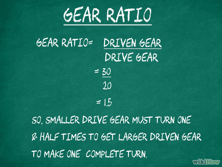
A good understanding of gear ratio calculations will allow you to fine-tune your car's performance characteristics - namely, acceleration and top speed. Gear ratios determine the load on the engine, and this affects acceleration and top speed. Knowing the right way to change gear ratios or other elements of a car, based on precise calculations, can make the difference between winning and losing. In addition, gear ratios are the basis for most other car performance calculations, so it's good to know how to determine these ratios.
Gear ratios tell you the amount of downshift in the transmission. Combustion engines have too much RPM and too little torque to be efficient if the engine is directly attached to the wheels. The car is unlikely to go anywhere with current wheels, or you'll need to use coin-sized wheels. Just as a hoist allows a mere mortal to lift tons of weight by himself, downshifting your car's transmission multiplies the torque to increase the small amount of engine torque, and this reduces the crankshaft RPM to a manageable amount so that the wheels turn at a more appropriate speed.

More than two gears
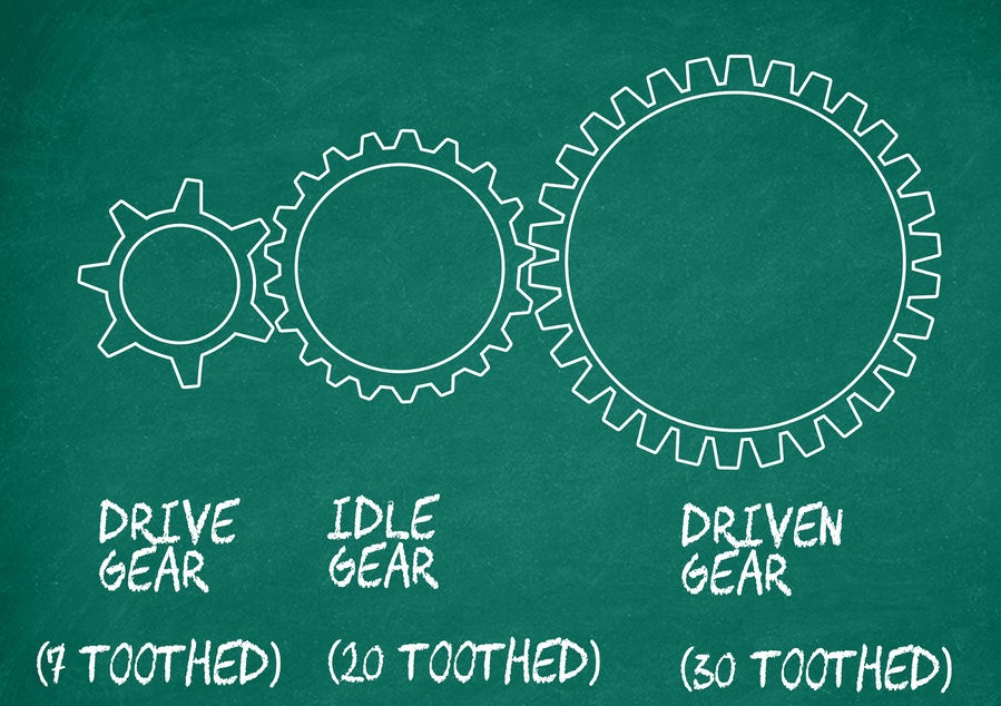
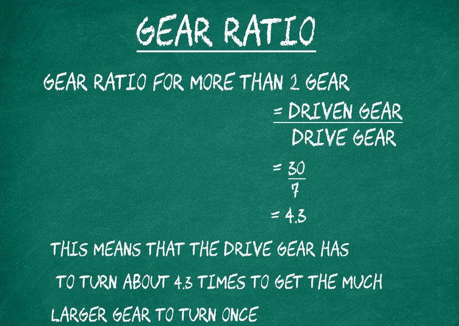
In other words, the gear ratio describes how the initial energy received from the engine or any other source of energy (water, wind wheel, turbine, etc.) changes when it is transmitted. Throughout the history of the development of technology, mankind has created a wide variety of gears, for each of which there is a gear ratio, which is a quotient of dividing the speed of the leading link by the speed of the follower.
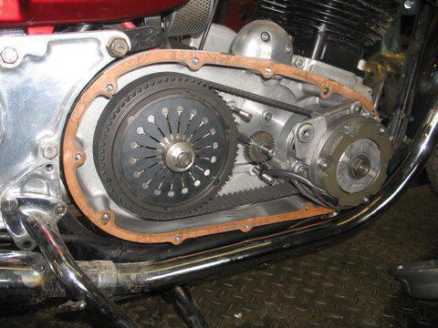
A belt drive is called two pulleys that connect the belt, as shown in the figure. It is possible that it was one of the first methods used by man. The material used to make the belt changed, its shape changed, but the gear ratio remained unchanged, defined as the frequent division of the speed of the drive shaft by the speed of the driven one, or as a result of dividing the number of revolutions of these shafts (n1 / n2 or? 1 /? 2) . For a belt drive, it can be calculated using the diameters (radii) of the pulleys. The gear ratio in this case is also determined as a quotient of the division of revolutions. If during the conversion of energy the number of revolutions decreases, that is, the gear ratio is greater than 1, then the gear will be downshift, and the device itself is called a gearbox. If the result is less than one, then the device is called a multiplier, although it also acts as a reducer, only a reduction. The gear ratio of the gearbox allows you to reduce the number of revolutions (angular speed) coming from the drive shaft to the driven one, while increasing the transmitted torque. This property of the gearbox makes it possible for engineers to achieve changes in the parameters of the transmitted energy when designing various devices, and the gear ratio of the gearbox serves as a powerful tool in solving the problem. Despite its considerable age, the belt drive is still working on a car, it is used as a drive for a generator, a gas distribution mechanism, and also in some other cases.
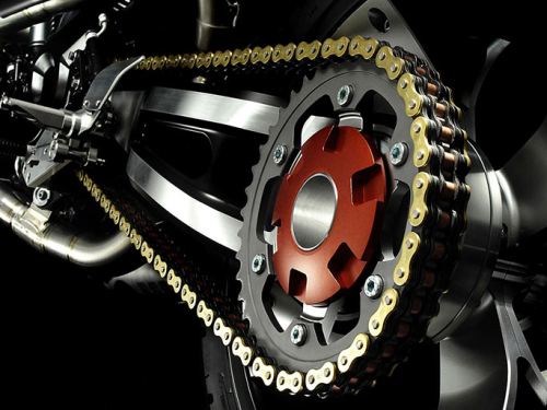
A distinctive feature of the chain drive is an increased noise level, as well as wear when operating at high speeds, therefore, if necessary, it is best to use it after reducing the speed. In a car, it is possible to use a chain drive for a timing drive, however, the limitation of such an application is the increased noise level during its operation.
GEAR RATIO
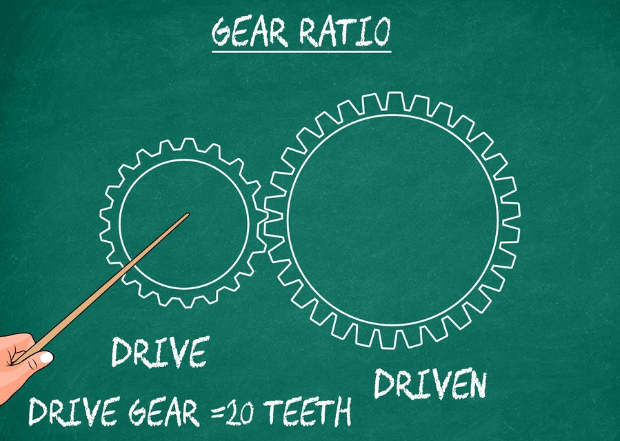
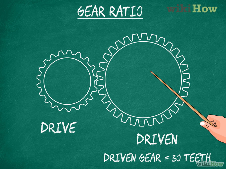
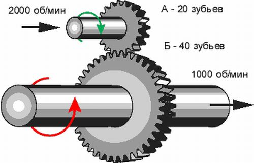
This is the name of a mechanism that uses wheels with teeth in engagement. It is considered the most rational and in demand for mechanical engineering. There are many different options for manufacturing such wheels, differing in the location of the axles, the shape of the teeth, the way they mesh, etc. As in the case of a chain, for a gear, the gear ratio is determined by dividing the number of gear teeth (z2 / z1). The variety of options for constructing gears makes it possible to use them in different conditions, from low-speed gearboxes to high-precision drives.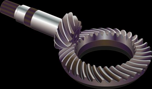
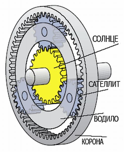
With any use of the planetary gearbox, one of its three elements will be stationary. In such a planetary version of the construction of gears, in relation to a simple gear or belt, it is possible to obtain a significant change in torque with a small number of wheels and dimensions of the device. In a car, such a planetary device has its own scope - as part of an automatic transmission, as well as in hybrid vehicles, to ensure the joint operation of an internal combustion engine and an electric motor. The planetary gearbox is widely used in tracked vehicles.
ABOUT MAIN COUPLE
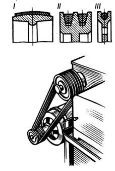
Almost all types of gears are used in a car - the torque from the engine goes through a chain of various devices and undergoes changes, starting from the gearbox, the main pair, and ending with the wheels of the car. All gear ratios for the gearbox and the main pair directly affect the dynamics of the car. Therefore, in order to ✔ reduce the switching frequency; ✔ the possibility of movement with a quiet ride at low engine speeds; ✔ increase the upper threshold of the speed of movement, gear ratios, including for the main pair, should be reduced. To improve acceleration dynamics, everything should be the other way around. The operation of various mechanisms and devices, including in a car, cannot occur without converting the energy used, both in magnitude and in direction. The gear ratio helps to evaluate and calculate the amount of the necessary change, as well as its consequences.The transfer of mechanical energy, carried out by a flexible connection due to friction between the belt and the pulley, is called belt. The belt drive consists of a driving and driven pulleys located at some distance from each other and enveloped by a drive belt (Fig. 182). The greater the tension, the angle of the belt around the pulley, and the coefficient of friction, the greater the transmitted load. Depending on the shape of the cross-section of the transmission belt, there are: flat-belt (Fig. 183, I), V-belt (Fig. 183, II) and round-belt (Fig. 183, III). The most widespread in mechanical engineering are flat and wedge-shaped belts. Flat belts experience minimal bending stress on the pulleys, wedge-shaped belts, due to the wedge effect with pulleys, are characterized by increased traction. Round belts are used in small machines, such as sewing and food processing machines, desktop machines and appliances.
Rice. 182
Rice. 183
To virtues belt drives include: the ability to transmit rotational motion over long distances (up to 15 m): simplicity of design and low cost; smooth running and unstressed work; ease of care and maintenance.
However, belt drives are bulky, short-lived in high-speed mechanisms, do not allow obtaining a constant gear ratio due to belt slippage, create increased loads on shafts and supports (bearings), since the total tension of the belt branches is much greater than the circumferential transmission force. In addition, during the operation of a belt drive, the possibility of slipping and breaking the belt is not ruled out, so these gears need constant supervision.
Types of flat belt drives
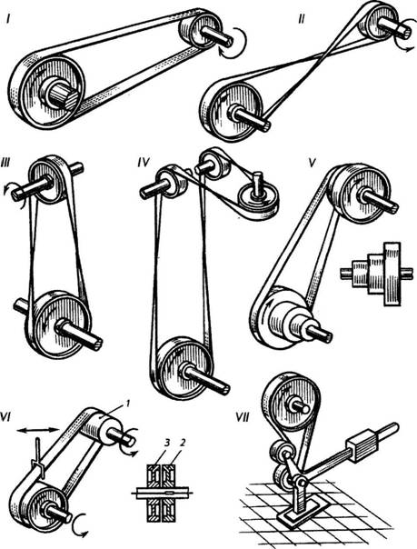
Depending on the location of the axes of the pulleys and the purpose, the following types of flat belt drives are distinguished:
- open gear - with parallel axes and rotation of the pulleys in one direction (Fig. 184, I);
- cross transmission - with parallel axes and rotation of the pulleys in opposite directions (Fig. 184, II);
- semi-cross transmission - with intersecting axes (Fig. 184, III);
- angular gear - with intersecting axes (Fig. 184, IV); gear with stepped pulleys (Fig. 184, V), which allows you to change the angular velocity of the driven shaft at a constant speed of the drive. The pulley steps are arranged so that the smaller step of one pulley is opposite the larger step of the other, etc. To change the speed of the driven pulley, the belt is thrown from one pair of steps to another;
- transmission with an idle pulley (Fig. 184, VI), which allows you to stop the driven shaft when the drive rotates. A wide pulley 1 is mounted on the drive shaft, and two pulleys are mounted on the driven shaft: a working pulley 2, which is connected to the shaft with a key, and an idle pulley 3, freely rotating on the shaft. The belt connecting the pulleys can be moved on the go, connecting pulley 1 with pulleys 2 or 3, respectively turning on or off the driven shaft;
- a transmission with a tension roller that provides automatic belt tension and an increase in the angle of the belt around the smaller pulley (Fig. 184, VII).
Rice. 184
The flat-belt transmission is simple in its design, it is used at large center distances (up to 15 m) and high speeds (up to 100 m/s) with reduced durability.
V-belt transmission
In a V-belt transmission, a flexible connection is carried out by a trapezoidal section drive belt with a profile angle? equal to 40° (in the undeformed state). Compared to a flat belt, the V-belt transmits more traction, but the transmission with such a belt has a reduced efficiency.
V-belt transmissions are advisable to use with large gear ratios, small center distances and vertical shaft axes. Belt speed V-belt transmission must not exceed 30 m/s. Otherwise, the V-belts will vibrate.
V-belts for general purpose drives are standardized by GOST 1284.1-89.
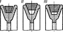
When installing a V-belt drive, special attention is paid to the correct installation of the V-belt III in the groove of the pulley rim (Fig. 185).
Rice. 185
Belt drive parts
Drive belts . Any drive belt serves as a traction body. It must have a certain traction ability (transmit a given load without slipping), have sufficient strength, durability, wear resistance, good grip on the pulley and low cost.
Flat belts are made in different widths, designs and from various materials: cotton, rubberized, woolen fabrics and leather. The choice of material for the belts is determined by the working conditions (atmospheric influences, harmful fumes, temperature changes, shock loads, etc.) and traction. Drive belts (rubberized) are standardized.
There are two types of V-belts: fabric cord and cord cord. In cord fabric belts (Fig. 186, I), the cord is made in the form of several layers of cord fabric with a base in the form of twisted cords 0.8-0.9 mm thick. In cord belts (Fig. 186, II), the cord consists of a single layer of cord wound along a helical line and enclosed in a thin layer of rubber to reduce friction. These belts are used in high speed transmissions and are flexible, reliable and durable.

Rice. 186
Note. Cord - a strong twisted thread made of cotton or artificial fiber.
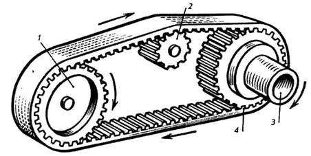
AT last years in domestic engineering, toothed (polyamide) belts are increasingly being used. These belts combine in their design all the advantages of flat belts and toothed gears (Fig. 187). On the working surface of the belts 4 there are protrusions that engage in the protrusions on the pulleys 1,2 and Z. Polyamide belts are suitable for high-speed transmissions, as well as for transmissions with a small center distance. They allow significant overloads, are very reliable and durable.
Rice. 187
The ends of the belts are connected by gluing, stitching and metal connectors. gluing homogeneous belts (leather) are carried out along an oblique cut at a length equal to 20 ... 25 times the thickness of the belt (Fig. 188, I), and ply belts - along a stepped surface with at least three steps (Fig. 188, II) . The joints of rubberized belts are vulcanized after gluing.
stitching used for all types of belts. It is produced by means of sinew strings or rawhide thongs (Fig. 188, III). Butt stitching with vein strings with inclined punctures is considered more perfect and reliable (Fig. 188, IV).
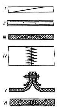
Rice. 188
Mechanical connectors apply to all belts, except for high-speed ones. They allow for a quick connection, but increase its mass (Fig. 188, V). Especially Good work provide hinged connections with wire spirals (Fig. 188, VI). The spirals are threaded through a series of holes, and after pressing they compress the belt. The hinge is created as a result of combining the spirals and threading the axis through them.
Pulleys. For flat belts, the most acceptable form of the pulley surface is a smooth cylindrical surface (Fig. 189, I).
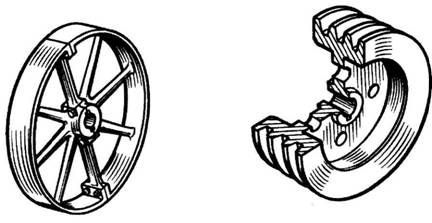
Rice. 189
To center the belt, the surface of the driven pulley is made convex, and the leading one is cylindrical (at v<= 25 м/с оба шкива делают выпуклыми).
For V-belts, the working surface is the sides of the V-grooves (Fig. 189, II) in the rim of the pulleys. The number and dimensions of these grooves are determined by the belt profile and the number of belts.
Pulleys are cast from cast iron, aluminum alloys, plastics and welded from steel. Cast iron pulleys are solid and split, consisting of two halves, which are bolted at the rim and bushing. Split pulleys can be easily removed from the shaft without lifting the shaft from the bearings.
A belt drive is a mechanism for transferring energy with a drive belt using friction or engagement forces. The amount of load to be transferred depends on the tension, wrap angle and coefficient of friction. The belts go around pulleys, one of which is the leading one, and the other is the driven one.
Advantages and disadvantages
Belt drive has the following positive properties:
- noiselessness and smoothness in work;
- high manufacturing precision is not required;
- slippage during overloads and vibration smoothing;
- no need for lubrication;
- low cost;
- the possibility of manual change of transmission;
- ease of installation;
- no damage to the drive when the belt breaks.
Disadvantages:
- large pulley sizes;
- violation of the gear ratio when the belt slips;
- little power.
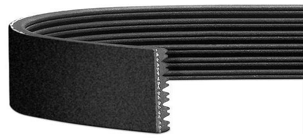
Depending on the type, the belt is flat, wedge, round and toothed. This belt drive element can combine the advantages of several types, for example, poly V-belt.
Areas of use
- The flat belt drive is used on machine tools, sawmills, generators, fans, and wherever greater flexibility is required and slippage is tolerated. For high speeds, synthetic materials are used, for lower speeds, cord fabric or rubberized materials are used.
- Belt drive with V-belts is used for agricultural machinery and cars (fan), in heavily loaded and high-speed drives (narrow and normal section).
- CVTs are needed where the speed of rotation of industrial machines is infinitely adjustable.
- Timing belt drives provide the best transmission performance in industrial and consumer applications where durability and reliability are required.
- Round belts are used for low power.
materials
Materials are selected to the operating conditions, where load and type are of primary importance. They are as follows:
- flat - leather, rubberized with stitching, whole-fabric wool, cotton or synthetic;
- wedge - a reinforcing layer in the center with a rubber core and a woven tape on the outside;
- toothed - a carrier layer of a metal cable, a polyamide cord or fiberglass in a rubber or plastic base.
The surfaces of the belts are covered with impregnated fabrics to increase wear resistance.
Flat belt drive belts
The transmission types are as follows:
- Open - with parallel axes and rotation of the pulleys in the same direction.
- Pulleys with steps - you can change the speed of the driven shaft, while the drive shaft has constant speed.
- Cross, when the axes are parallel, and the rotation occurs in different directions.
- Semi-cross - the axes of the shafts are crossed.
- With a tension roller that increases the angle of wrapping of a pulley of a smaller diameter.

The open type belt drive is used for high speed and large center distance operation. High efficiency, load capacity and durability make it possible to use it in industry, in particular for agricultural machines.
V-belt transmission
The transmission is characterized by a trapezoidal cross-section of the belt and the surfaces of the pulleys in contact with it. The transmitted efforts in this case can be significant, but its efficiency is small. V-belt transmission is characterized by a small distance between the axles and a high gear ratio.
timing belts
The transmission is used for high speed with a small distance between the axles. It has the advantages of belt and chain drives at the same time: work under high loads and with a constant gear ratio. The power of 100 kW can be provided mainly by a toothed belt drive. In this case, the revolutions are very high - the speed of the belt reaches 50 m / s.
Pulleys
The belt drive pulley can be cast, welded or prefabricated. The material is selected depending on the speed. If it is made of textolite or plastic, the speed is not more than 25 m/s. If it exceeds 5 m / s, static balancing is required, and for high-speed gears - dynamic.
During operation, pulleys with flat belts experience wear of the rim from slippage, breakage, cracks, and breakage of the spokes. In V-belt drives, the grooves on the working surfaces wear out, the shoulders break, and imbalance occurs.
![]()
If a hub hole is produced, it is bored, and then the sleeve is pressed in. For greater reliability, it is made simultaneously with internal and external keyways. The thin-walled sleeve is mounted on glue and bolted through the flange.
Cracks and kinks are welded, for which the pulley is first heated to eliminate residual stresses.
When turning the rim for a V-belt, it is allowed that the rotational speed can vary up to 5% of the nominal.
Gear calculation
All calculations for any type of belts are based on the determination of geometric parameters, traction and durability.
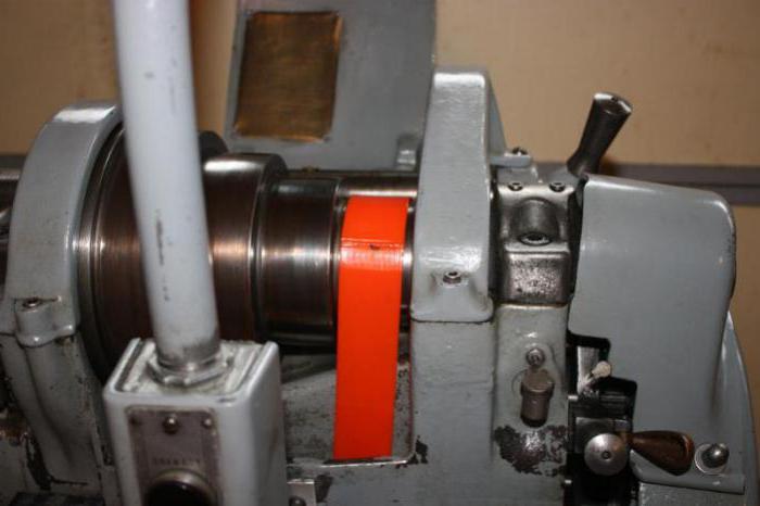
1. Determination of geometric characteristics and loads. It is convenient to consider the calculation of a belt drive using a specific example. Let it be necessary to determine the parameters of a belt drive from an electric motor with a power of 3 kW to a lathe. Shaft speeds are, respectively, n 1 = 1410 min -1 and n 2 = 700 min -1 .
The usually narrow V-belt is selected as the most commonly used. The nominal torque on the drive pulley is:
T1 = 9550P 1: n 1 = 9550 x 3 x 1000: 1410 = 20.3 Nm.
From the reference tables, the diameter of the drive pulley d 1 = 63 mm with the SPZ profile is selected.
Belt speed is defined as follows:
V \u003d 3.14d 1 n 1: (60 x 1000) \u003d 3.14 x 63 x 1410: (60 x 1000) \u003d 4.55 m / s.
It does not exceed the permissible, which is 40 m / s for the selected type. The diameter of the large pulley will be:
d2 \u003d d 1 u x (1 - e y) \u003d 63 x 1410 x (1-0.01): 700 \u003d 125.6 mm.
The result is reduced to the nearest value from the standard series: d 2 = 125 mm.
The distance between the axles and the length of the belt are found from the following formulas:
a \u003d 1.2d 2 \u003d 1.2 x 125 \u003d 150 mm;
L \u003d 2a + 3.14d cp + ∆ 2: a \u003d 2 x 150 + 3.14 x (63 + 125): 2 + (125 - 63) 2: (4 x 150) \u003d 601.7 mm.
After rounding to the nearest value from the standard range, the final result is obtained: L= 630 mm.
The center distance will change, and it can be recalculated again using a more accurate formula:
a \u003d (L - 3.14d cp): 4 + 1: 4 x ((L - 3.14d cp) 2 - 8∆ 2) 1/2 \u003d 164.4 mm.
For typical conditions, the power transmitted by one belt is determined by nomograms and is 1 kW. For a real situation, it must be refined by the formula:
[P] = P 0 K a K p K L K u .
After determining the coefficients according to the tables, it turns out:
[P] = 1 x 0.946 x 1 x 0.856 x 1.13 = 0.92 kW.
The required number of belts is determined by dividing the power of the electric motor by the power that one belt can transmit, but at the same time the coefficient C z \u003d 0.9 is also introduced:
z \u003d P 1: ([P] C z) \u003d 3: (0.92 x 0.9) \u003d 3.62 ≈ 4.
The belt tension force is: F 0 \u003d σ 0 A \u003d 3 x 56 \u003d 168 H, where the cross-sectional area A is according to the reference table.
Finally, the load on the shafts from all four belts will be: F sum = 2F 0 z cos(2∆/a) = 1650 H.
2. Durability. The calculation of the belt drive also includes the determination of durability. It depends on the fatigue resistance, determined by the magnitude of the stresses in the belt and the frequency of their cycles (the number of bends per unit time). From the resulting deformations and friction inside the belt, fatigue destruction occurs - tears and cracks.
One load cycle manifests itself in the form of a fourfold change in stress in the belt. The frequency of runs is determined from the following relationship: U = V: l< U d ,
where V - speed, m/s; l - length, m; U d - allowable frequency (<= 10 - 20 для клиновых ремней).
3. Calculation of toothed belts. The main parameter is the modulus: m = p: n, where p is the circumferential step.
The value of the module depends on the angular velocity and power: m = 1.65 x 10⁻³ x (P 1: w 1) 1/3.
Since it is standardized, the calculated value is reduced to the nearest value of the series. For high speeds, higher values are taken.
The number of teeth of the driven pulley is determined by the gear ratio: z 2 = uz 1.
The center distance depends on the diameters of the pulleys: a \u003d (0.5 ... 2) x (d 1 + d 2).
The number of teeth on the belt will be: z p = L: (3.14m), where L is the approximate calculated length of the belt.
After choosing the nearest standard number of teeth, then determine the exact length of the belt from the last ratio.
It is also necessary to determine the width of the belt: b = F t: q, where F t is the circumferential force, q is the specific belt tension, selected by the module.
The load on the shafts will be: R = (1...1.2) x F t .
Conclusion
The performance of belt drives depends on the type of belts and their operating conditions. The correct calculation will allow you to choose a reliable and durable drive.